I hope everyone is doing well.
It’s hard to believe that I have not updated the simpit build since September 25th! I did take some time away for house and family projects but I have restarted as you will see below.
Take care
Ed
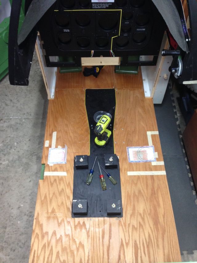
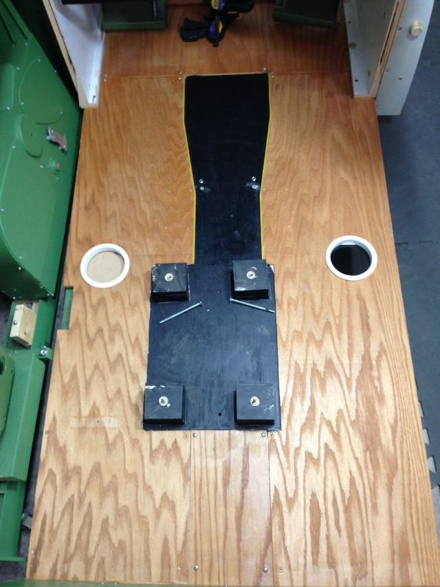
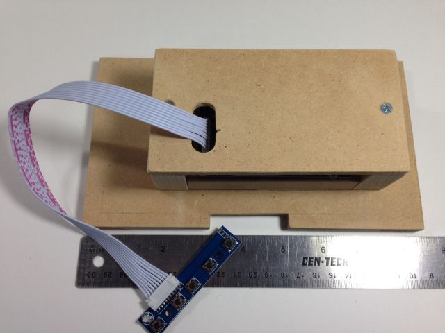
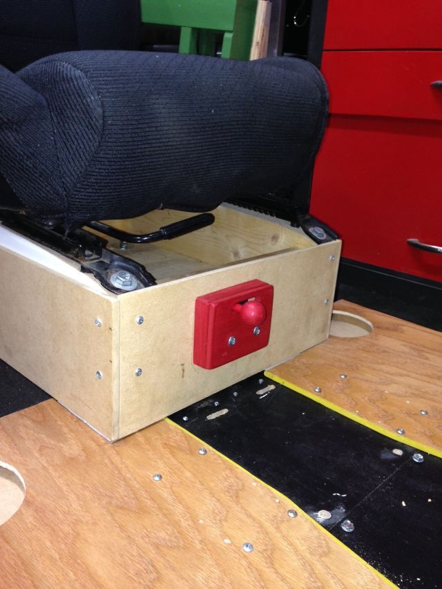
The goal of this pit is to use all functions available in the Mustang cockpit that FSX and A2A supports so I made a control lock device. The real lock is at the base of the control stick. Since that area is not available in my pit I chose to mount the device on the front of the seat base.
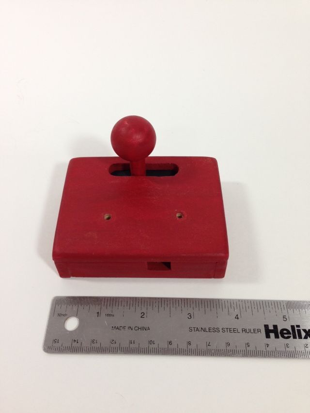
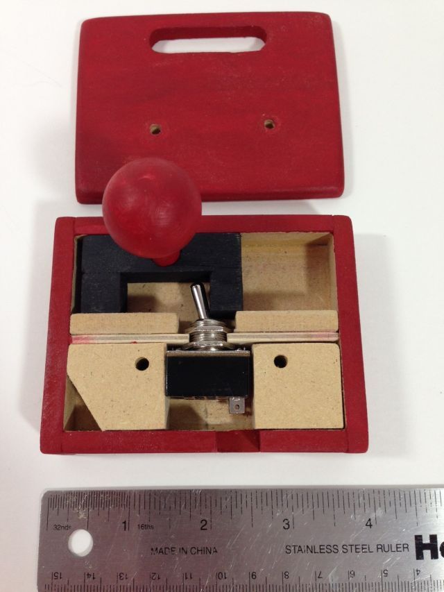
Here you can see a simple toggle switch mounted in a box. The switch is activated by sliding the knob from side to side.
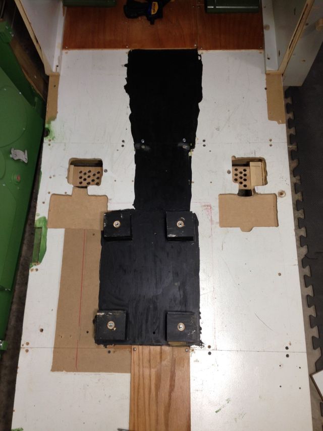
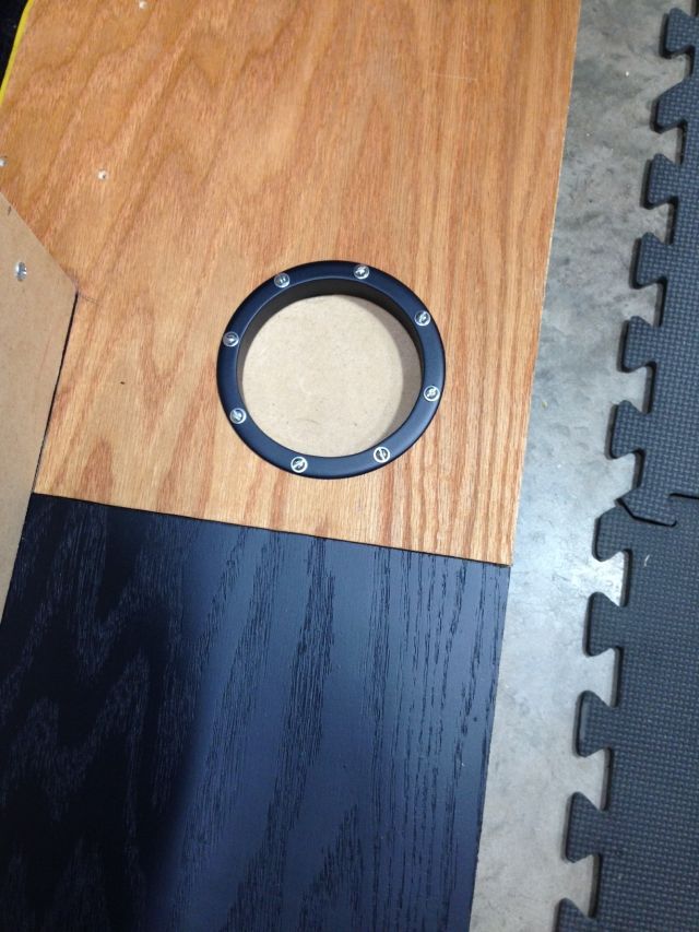
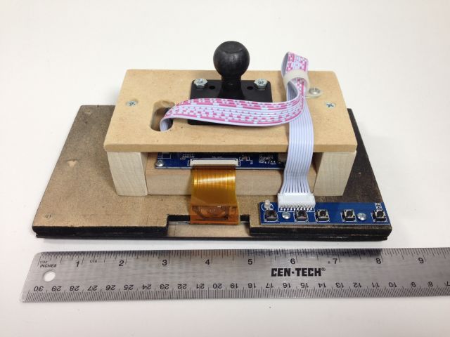
Mounted
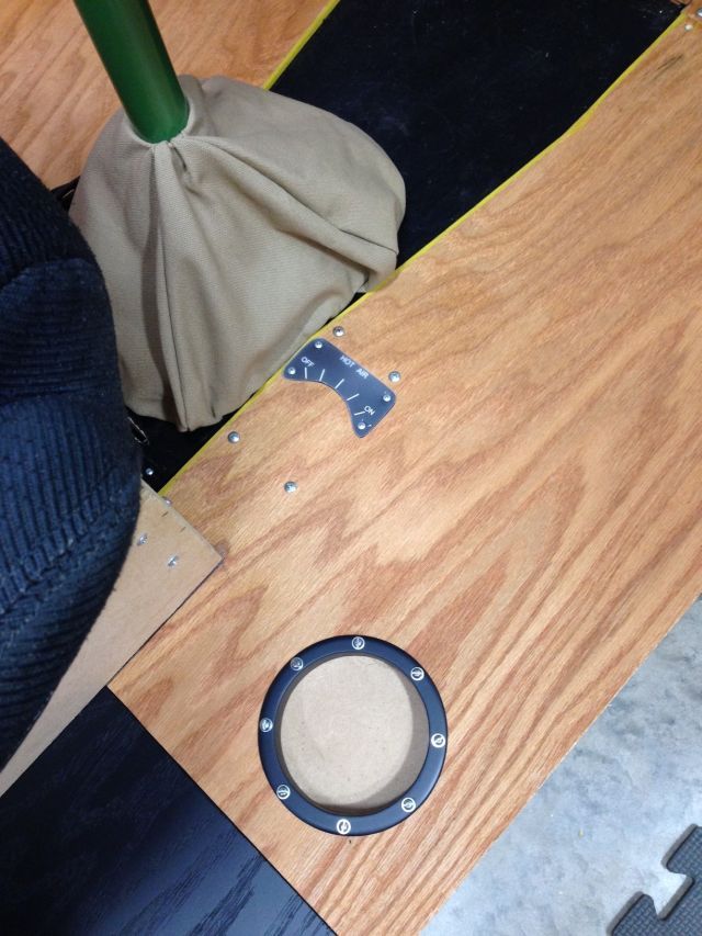
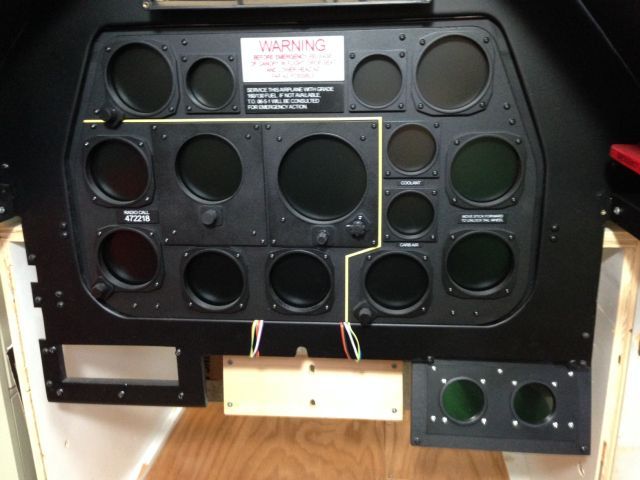
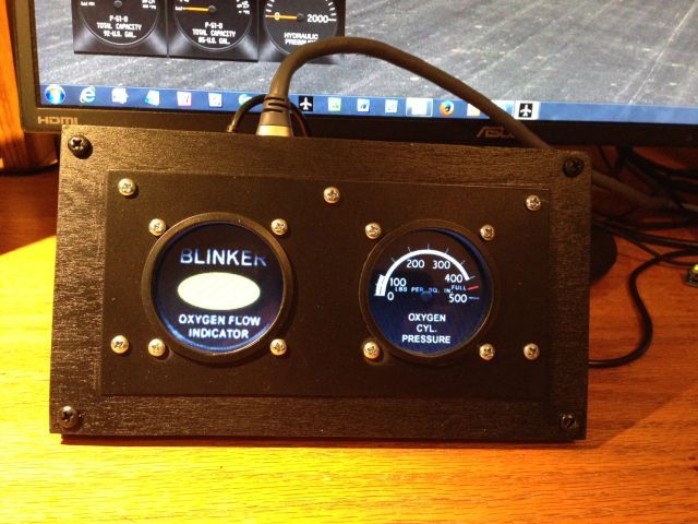
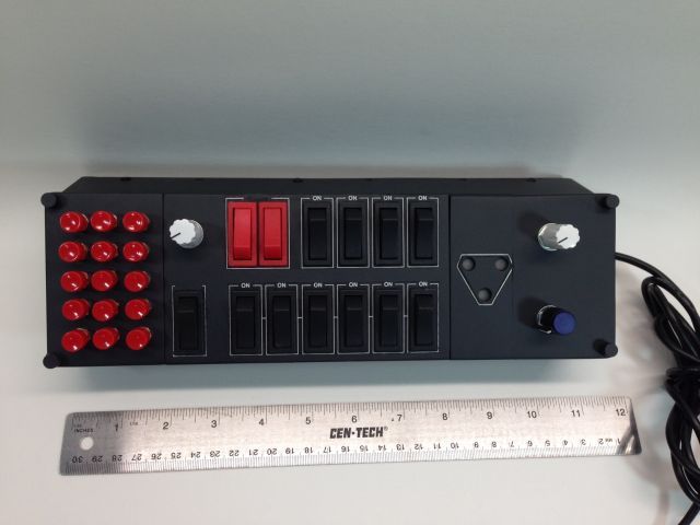
I also have worked on the modified Saitek Switch Panel. All that is left is to add the labels.
I have been dreading the wiring part of the project but it is now underway. My pit is being built in my garage workshop but will be used in my home office. (My wife may or may not have mentioned that it could stay in the garage.) The pit is 38 inches wide and has to fit through a door only 29 ½ wide so concessions were made to get it in the house. I intend to complete 95% of the pit in the garage then take it apart for the move.
The pit consists of the following components.
Floor on wheels
Seat
Front cowling area
Windshield and shroud
Left side, right side and back
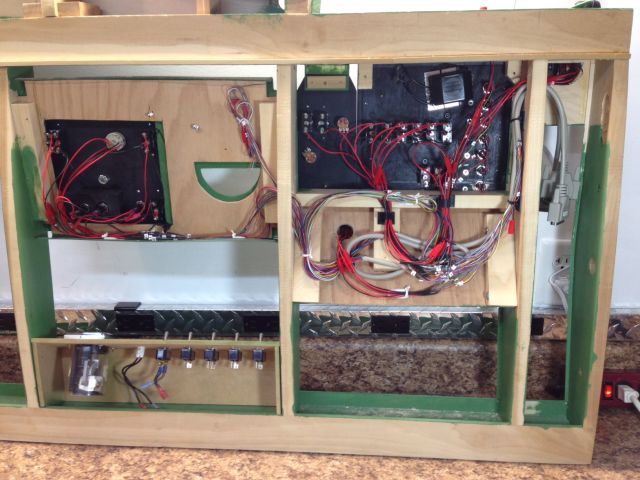
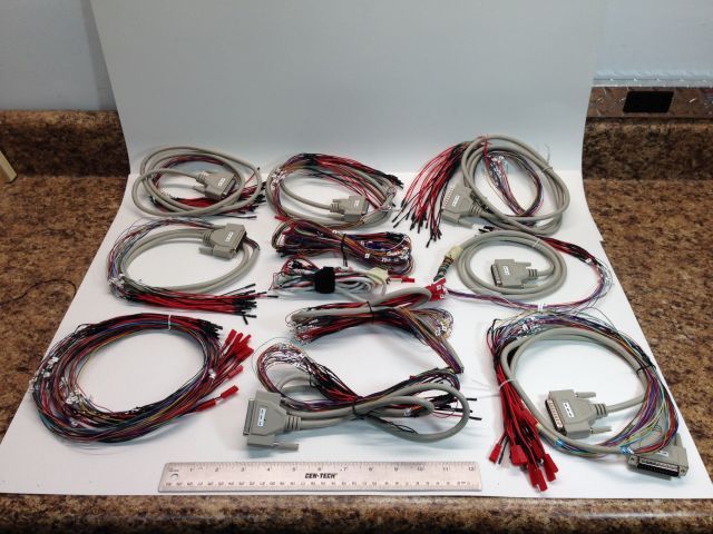
I have installed all of the panels in the pit sections and the wiring is almost complete. All of the connections will be made with separate wiring harnesses in two parts. Part A of the harness is in the main pit and part B is in the cowling section that will hold all of the USB panels. I used DB25 cables because they have 25 wires and with the Male/Female connections they give me a quick connect setup. Once the components are installed I will connect the DB M/F fittings and be ready to start programming control settings. Sorry, this has been a long explanation so I hope the following pictures will help.
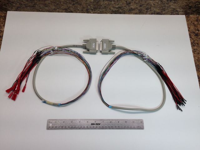
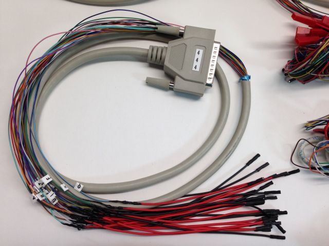
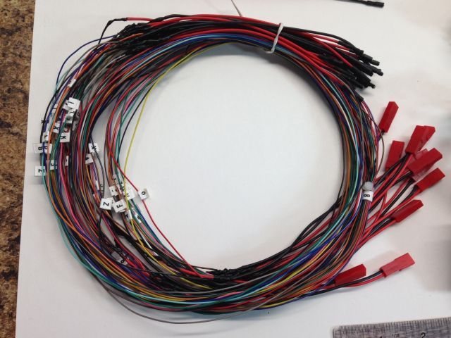
Here you can see a finished harness. The DB25 cable has been cut and you can see how it will reconnect using the M/F in the pit. I decided I did not want to solder the 2 or 3 pin mini fittings that came with the USB boards so I installed fittings intended for RC devices. I did solder them to the wires but at least it was not as small an area as the mini fittings. I then coated the soldered areas with liquid electrical tape. Each main cable, there are 12, and each individual wire is labeled for installation. I had to use a spreadsheet to keep track of the cables, wires and boards for their final connection.
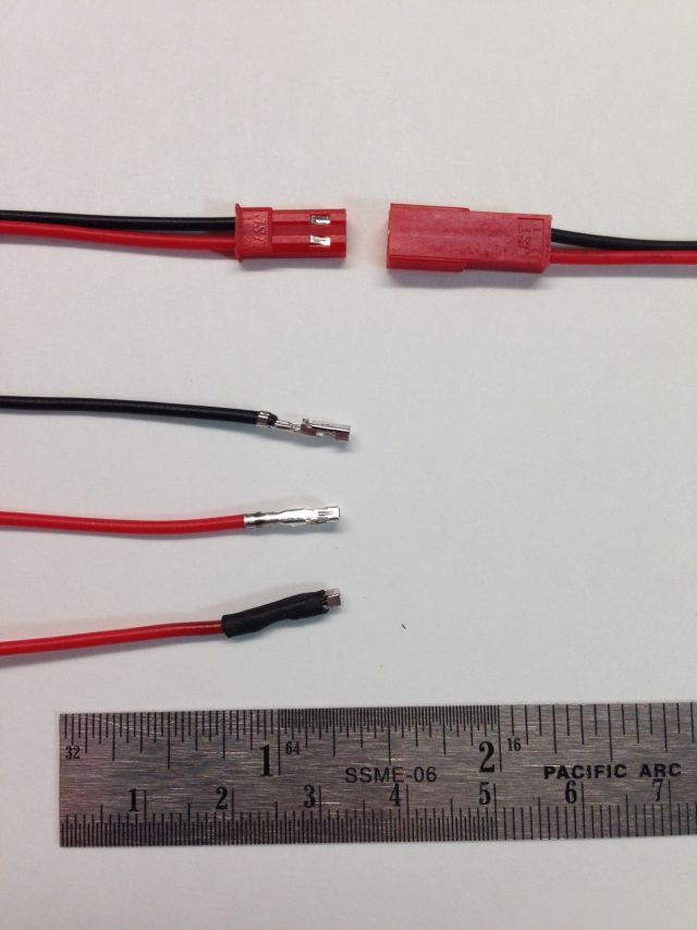
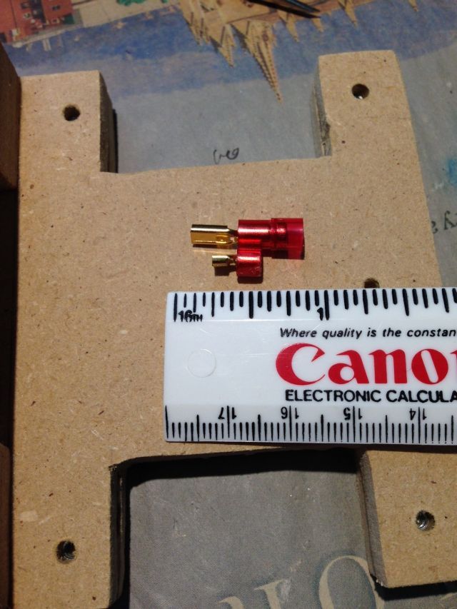
The “male†RC fittings did align with the pins on the USB boards but due to their thickness they could not be used. You can see one at the top left of the following pic. So I inserted an awl into the silver area and released the individual wires. I then slid shrink tape over the bare metal and applied heat.
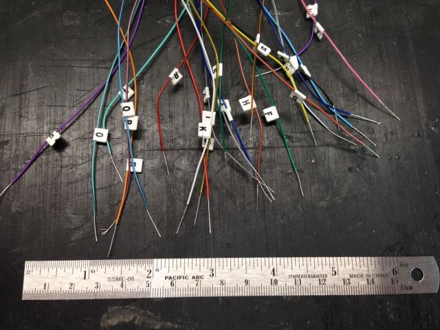
The 25 wires cut and labeled
Again, avoiding solder, I used crimp on fittings. Some areas where the connectors went to the switches were too tight for standard fittings. I found 3/32 fittings that fit the switches then trimmed them to fit the area.
The 3/32 fittings worked here without trimming but I did cut slots in the mounting panel.
A close-up of side B of one harness
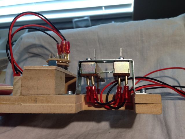
This gives you an idea of the wires going into the pit and this is not all of them!
The Saitek Panel will be mounted to the MIP so no quick connect was needed for the 25 wires.
This is the back of the right side of the pit. After I took this pic I added another 25 wires for the radio and electrical cables for the environmental switches that control the fans and lights.