Page 1 of 1
Question about Nav Instruments on American Bombers/Fighters
Posted: 01 Sep 2006, 22:47
by Jawaka
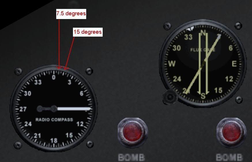
The Radio Compass and Flux Gate Compass on the B17/B24/B29/P51/P47 have major tick marks every 7.5 degress.
Is that correct? If yes, why? Is there some reason why it's not every 10 degrees?
Thanx
Posted: 03 Sep 2006, 17:15
by Jawaka
Anyone?
Posted: 03 Sep 2006, 22:08
by Jawaka
Maybe a pic would help:
Posted: 03 Sep 2006, 22:34
by 46th_Terror
I dont know the real answer but looking at it. I would assume it has to do witht he 0,90,180,270 degree standards. North south east and west. devided out it comes out pretty even that way. If done on a 10 degree it would be harder to read as the numbers would be to small. But if a real pilot has a true answer I am interested also.
Posted: 04 Sep 2006, 03:48
by Osram
I would be very surprised if with a bit of search you could not find the original navigation manuals and even instruments like triangle calculator on ebay. I have a few, but not US WWII, sorry.
Posted: 04 Sep 2006, 22:42
by Jawaka
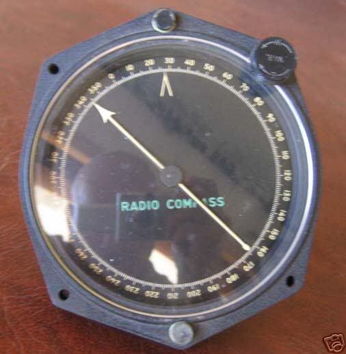
This was a B17 radio compass up for auction on Ebay. Obviously not the same model but clearly marked in 10s of degrees. I have yet to find any navigation instrument that doesn't use the 10 degree demarcation.
Any military pilots or maybe someone from Shockwave can shed some light?
Posted: 05 Sep 2006, 04:46
by ROB - A2A
Hi, Jawaka. The radio compass and flux gate arn't quite correct.
The radio compass should have five, and the flux gate fourteen marks beetween the main (digit) marks. So, it gives 10 degrees system.
As the author I'm ashamed of myself

regards
ROB
Posted: 05 Sep 2006, 07:27
by Snuffy
Don't ya just hate it when bald headed people place objects for sale on E-Bay?
Looking hard enough at the glass on the guage above, you can see the reflection of the seller and his camera.
Off topic I know ... but there have been a host of images from E-Bay where reflections of the seller and what they were or were not wearing at the time of the article being photographed.
Posted: 05 Sep 2006, 17:56
by Jawaka
ROB wrote:Hi, Jawaka. The radio compass and flux gate arn't quite correct.
The radio compass should have five, and the flux gate fourteen marks beetween the main (digit) marks. So, it gives 10 degrees system.
As the author I'm ashamed of myself
regards
ROB
Hey ROB. I can see how it was easy to miss. Certainly looks correct. It was when I started to try doing some extreme poor visibility navigation and started to look much more closely.
Any possibility of a fix?
Snuffy_Haden wrote:Don't ya just hate it when bald headed people place objects for sale on E-Bay?
LOL, I didn't notcie that at first. Pretty funny.
Posted: 18 Dec 2006, 05:58
by ROB - A2A
Jawaka wrote:
Hey ROB. I can see how it was easy to miss. Certainly looks correct. It was when I started to try doing some extreme poor visibility navigation and started to look much more closely.
Any possibility of a fix?
Sorry Jawaka, I havn't noticed your question. We have to wait for an occasion to get it fixed. However, if this fault is a serious trouble for you, send me a PM.
regards
ROB
Posted: 04 Feb 2007, 07:06
by 150GCT_Gielle
Hi!
Maybe this is a bit off topic, but someone could explain me how to activate the radio compass in the B-17?
I went through the manual but I didn't find anything about it.
Is that related to the VOR?
Posted: 04 Feb 2007, 10:13
by ROB - A2A
No, it's the NDB (ADF) related thing.
Use ADF Radio (SCR-269) to tune in.

regards
ROB
Posted: 05 Feb 2007, 02:19
by 150GCT_Gielle
Ok, thanks!

Re: Question about Nav Instruments on American Bombers/Fight
Posted: 24 Sep 2012, 15:53
by boeing377
The 4 band ADF control box pictured above isn't from the SCR 269 (which looks nearly identical but has 3 bands). The 4 band control box pictured is the C 4 ARN-7 control for the R-5 ARN-7 ADF receiver. SCR 269 receiver (BC-433) is very similar to R-5 ARN-7but omits the 100-200 Kc band. Post WW-2 surplus ARN-7 units were made into FAA legal MN 62 ADFs for civil airliners. The ARN-7 to MN 62 mod involved new front panel and LP 21 loop connectors and a few new circuit components, nothing major.
Mark