Page 32 of 33

Re: B-17 Enclosed Home Cockpit Project

Posted: 23 Mar 2017, 05:57
by boris4356
Killratio wrote:Nice work Bill..sorry I missed this back in Jan.
Thanks Darryl!

Bill

Re: B-17 Enclosed Home Cockpit Project

Posted: 10 Sep 2017, 17:40
by boris4356
My gauge TV monitor failed on me and I had to remove it and get a new one. What a major pain that was. First I had to remove the Co-pilot panel. I made a little stand to place it on so I could just move it out of the way without disconnecting anything. I then had to unbolt the yoke column and place it out of the way.I also had to remove the bolts from the throttle and centre panel and move it back. After that I removed the wood backplate that covered the TV bezels. After all that I was able to take the old TV out.

I bought a new Insignia 40" TV from Best buy. The Bezels are extremely thin, so I decided to mount it differently from the old one. I didn't need a wood backplate anymore, and I just used the stand that came with it. I also decided to remove the 2x4 supporting brace that ran under the front monitor so I could place the TV higher and closer. In order to do this I had to remove the 3 front monitors.


Image


Image


Image


After I removed the 2x4 supporting brace I needed a way to hold up and support the 3 front monitors. I used steel mending plates with lag bolts under each monitor frame connected to the back wall.


The top view of the brackets. There are two brackets for each monitor.

Image


The bottom view of the brackets

Image


Then I made the base for the TV. I just re-used the wood from the old base.


Image


The TV stand feet are at an angle so I added to the base. The TV just sits on top. Then The Co-Pilot Panel was put back in its original spot. The TV now sits directly under the monitor, and is 3 inches closer.


Image


While I had everything apart I decided to put plexiglass windows over the three front monitors so I would get the same type of view I get from the two side plexiglass windows. It is now much more realistic. It actually looks like you are looking out a window instead of at a computer monitor.


Setting up and Measuring for cutting


Image


To cut the plexiglass, I used a scoring tool made for cutting plexiglass. I have used a utility knife in the past, but it was not as clean and easy as this tool makes it. I left the plastic cover on so I wouldnt scratch the windows.The cut is not completely smooth, but that was not a concern as it would be covered.


Image


After the score is made you just snap the piece off.


Image


Lining up the window with the aluminum flashing holes. The window just sits in front of the frame, and the aluminum flashing is put back on over top. Then I drilled the pilot holes in the plexiglass for the screws.


Image


Image


Then I put everything back in place.


Image


Image


Image


Image


Image

Bill

Re: B-17 Enclosed Home Cockpit Project

Posted: 12 Sep 2017, 00:07
by Killratio
Beautiful work Bill!!

Damned maintenance takes up as much time as flying, doesn't it!

Darryl

Re: B-17 Enclosed Home Cockpit Project

Posted: 12 Sep 2017, 06:45
by boris4356
Killratio wrote:Beautiful work Bill!!

Damned maintenance takes up as much time as flying, doesn't it!

Darryl
Thanks Darryl!

That's for sure!

Bill

Re: B-17 Enclosed Home Cockpit Project

Posted: 12 Sep 2017, 09:21
by Gypsy Baron
Looking fantastic, Bill! Waiting now for some airborne pix :)

Paul

Image

Re: B-17 Enclosed Home Cockpit Project

Posted: 13 Sep 2017, 06:53
by boris4356
Gypsy Baron wrote:Looking fantastic, Bill! Waiting now for some airborne pix :)

Paul

Image
Thanks Paul!

Re: B-17 Enclosed Home Cockpit Project

Posted: 14 Sep 2017, 04:37
by Lewis - A2A
Awesome work, love the plexiglass over the monitor feature you got going on here. Amazing! 8)

thanks,
Lewis

Re: B-17 Enclosed Home Cockpit Project

Posted: 14 Sep 2017, 06:46
by boris4356
Lewis - A2A wrote:Awesome work, love the plexiglass over the monitor feature you got going on here. Amazing! 8)

thanks,
Lewis
Thanks Lewis!

Bill

Re: B-17 Enclosed Home Cockpit Project

Posted: 14 Sep 2017, 13:49
by Raceguy
Great update Bill!

Ed

Re: B-17 Enclosed Home Cockpit Project

Posted: 16 Sep 2017, 08:43
by boris4356
Raceguy wrote:Great update Bill!

Ed
Thanks Ed!

Bill

Re: B-17 Enclosed Home Cockpit Project

Posted: 20 Apr 2018, 19:35
by Samster
Amazing work you have there!

I have a question; Where do you get the Instrument panel for the B-17? What program?

Thanks,
-Sam

Re: B-17 Enclosed Home Cockpit Project

Posted: 27 Apr 2018, 08:26
by boris4356
Samster wrote:Amazing work you have there!

I have a question; Where do you get the Instrument panel for the B-17? What program?

Thanks,
-Sam
Hi Sam,

Sorry for taking so long to answer. I just saw this today as I only check here once in a while.

I used the 2D gauges from the WOP II B-17 and used Flight Sim Panel Studio from Flight 1 to make the panel.

Bill

Re: B-17 Enclosed Home Cockpit Project

Posted: 27 Apr 2018, 13:57
by Samster
Okay, thank you! No problem with the response time. I'm asking because I'm making a full sized instrument panel as well!

Re: B-17 Enclosed Home Cockpit Project

Posted: 07 May 2018, 07:41
by boris4356
Samster wrote:Okay, thank you! No problem with the response time. I'm asking because I'm making a full sized instrument panel as well!
Your welcome!

Bill

Elevator Trim Wheel

Posted: 11 Jan 2019, 18:05
by boris4356
I have had an issue with my elevator trim wheel for quite a long time now where the gears go out of alignment and it needs to be constantly readjusted. This was a major irritation as it was not a simple process. The actual gear realignment was easy, but in order to access them, I had to unbolt my yoke column and move it out of the way. Then unbolt the throttle quadrant pedestal base and move it back to be able to access the rotary controller and the gears inside.

In order for the shaft of the trim wheel, which is a 3/8 inch carriage bolt, the 3/8 inch hole that is drilled into the throttle quadrant pedestal base has to be made slightly larger so that it can spin freely and not end up acting as a nut by threading the hole when it is inserted. I used a nylock nut on each side of the pedestal wall tightened just to the point of letting the shaft spin without tightening.

Although good in theory, the problem with this design is that because the nuts on each side of the pedestal wall are not completely tightened the shaft does not spin true. Over time the hole gets slightly larger from wear, and the shaft wobbles around causing the gears to come out of alignment and either bind or sometimes just turn off each other and not make contact.

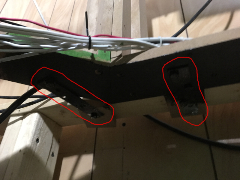
This is what the old gear design looked like:


Image


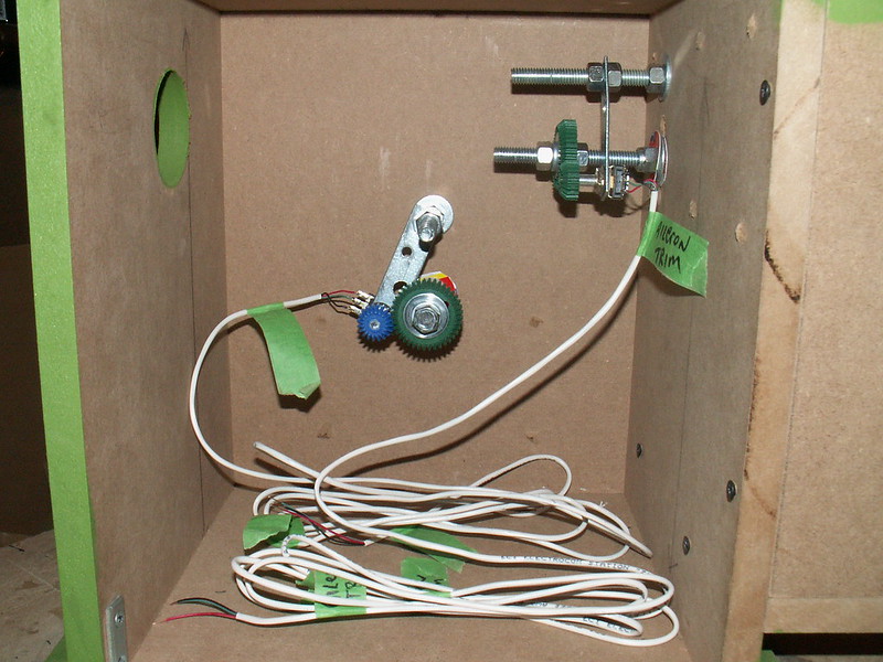
The main reason for using gears with potentiometers is to act as a step down. That is to reduce the rotation amount. For example I use them with my throttle levers. The travel the throttle lever goes through is much less than what the travel the potentiometers goes through so you use gears to accomplish this.

I am using Rotary Controllers and not potentiometers for the trim functions. A rotary controller just turns infinitely forward or backward not coming to a stop and not having a definitive travel length like a potentiometer has. Therefore gears are not needed with a rotary controller. It can just be connected directly to the shaft of the elevator trim wheel. I actually did this with my aileron trim wheel when I moved it from the throttle quadrant pedestal base to my icing controls box on the left side flight deck and didn`t realize at the time that this could work for my elevator and rudder trim wheels as well. In fact I didn`t realize it until after I completed the mod and began to write up this post that I had used this principle before.

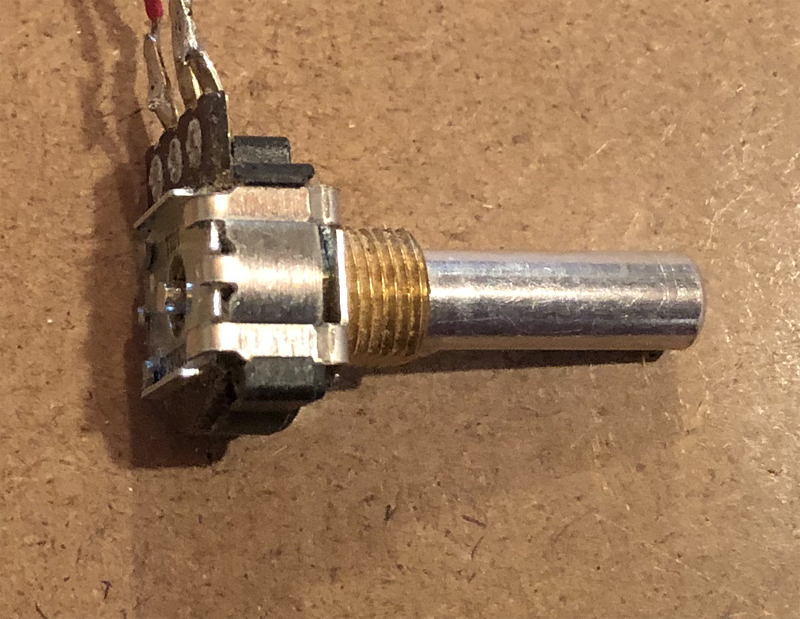
This is what a rotary controller looks like. Note that it just has a 1/4 inch smooth solid shaft with no knurling or split slots that you can use to attach it to something easily. It is too bad that it wasn`t threaded because they make a 3/8 inch to 1/4 inch metal coupler that I could have used to connect the rotary controller to the elevator trim shaft.


Image


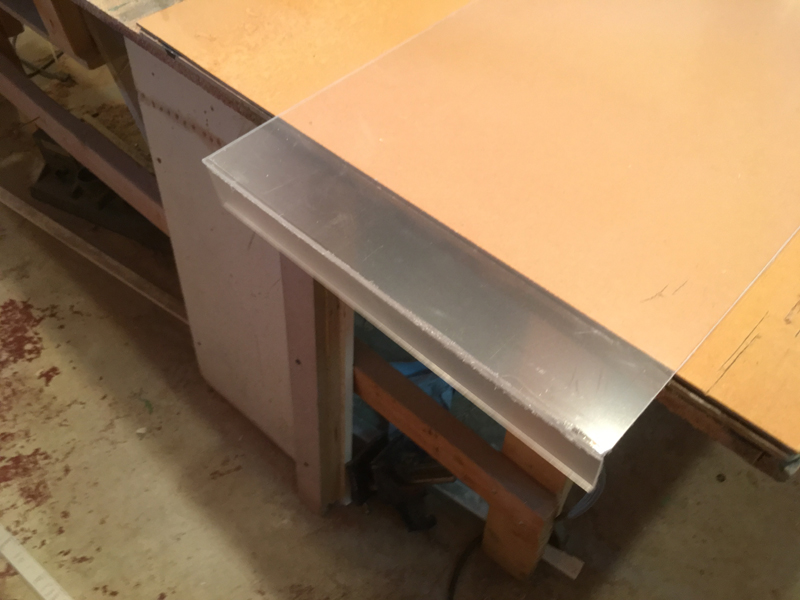
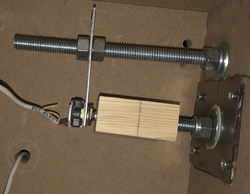
I decided to make a coupler out of wood and drill a 1/4 inch hole for the rotary controller in one end and a 23/64 inch hole drilled in the other end. I then inserted a 3/8 inch bolt into the 23/64 inch hole making it threaded.

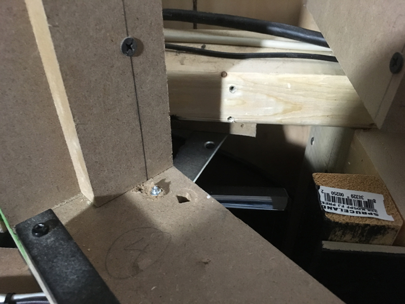
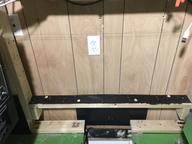
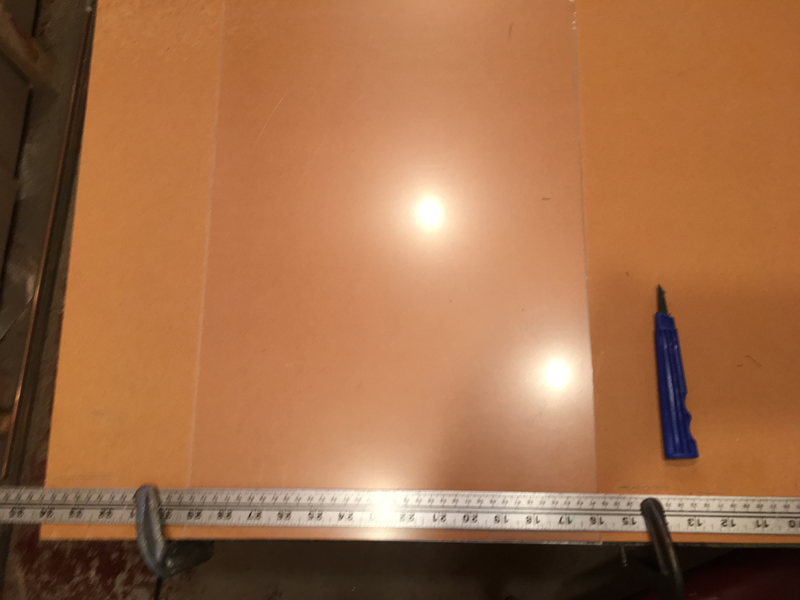
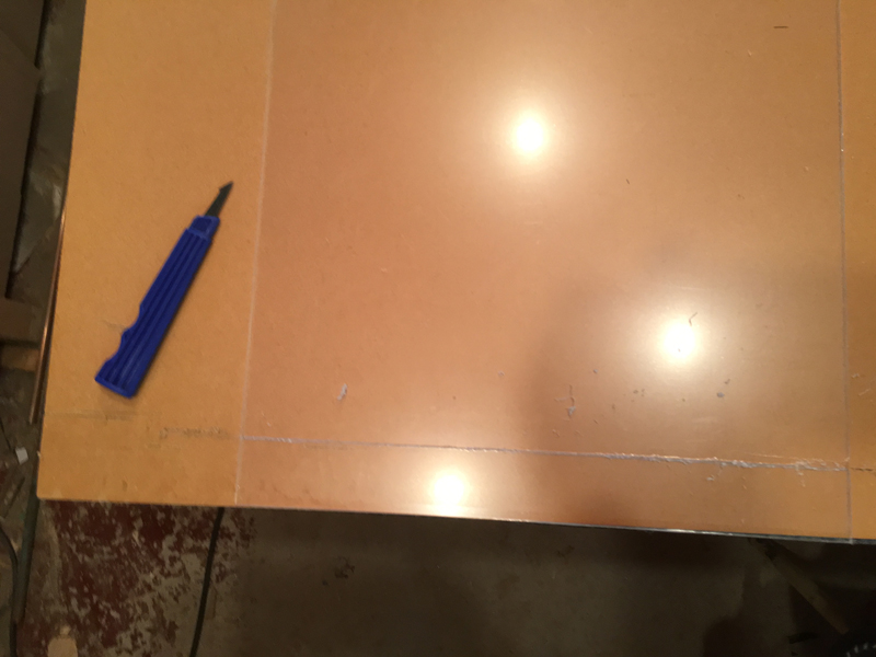
I made steel plates to put over the holes on each side of the base. This helps keep the shaft from wobbling and makes a smooth surface for the nyloc nuts to spin on. I put homemade plastic washers cut from a margarine container and large steel washers on each side of the hole as well. Then I put the elevator trim wheel shaft through the hole in the base and put the inside nyloc nut on. This nut can be tightened to allow for some friction so the wheel doesn`t turn too easily with no resistance.

Then I screwed the threaded end of the wood coupler onto the 3/8 inch carriage bolt of the elevator trim wheel turning it slightly farther than the threads for a snug fit. Then pushed the shaft of the rotary controller into the 1/4 inch hole. The shaft is just mere microns larger than 1/4 inch so when you push it on it is a snug fit. I just left the mending plate on the rotary controller and attached it to the top bolt in the same fashion as with the gear system I had. This is still needed to keep the rotary controller body from spinning instead of just the shaft. It also acts as a support so the shaft should not wobble.

I have had this in place for about a week now and it is working well. There is virtually no friction on the coupler itself, so I don`t foresee it loosening at all.


Image


Bill